Introduction
The micro X-ray fluorescence spectrometer (µ-XRF) at the Laboratory of Nuclear Instrumentation (LIN) was granted by FAPESP within the “Young Investigators Award” 2015/05942-0 coordinated by Asst. Prof. Hudson W.P. Carvalho. The project gathered a consortium of researchers (see below) to investigate the absorption, transport, accumulation and metabolism of nanomaterials by plants.
The LIN is part of the Divisão de Desenvolvimento de Técnicas Analíticas e Nucleares ( DVTEC ) of CENA-USP. For further information on our activities visit our webpage lin.cena.usp.br
µ-XRF
The EMU benchtop μ-XRF system consists in a cross-cutting equipment. It combines qualitative and quantitative elemental analysis with space resolution under atmospheric pressure or vacuum. Furthermore, XRF is a non-destructive technique, it presents simple operation and requires minimal or none sample preparation. Hence, it saves chemicals, time and manpower. All these features are essential for our study.
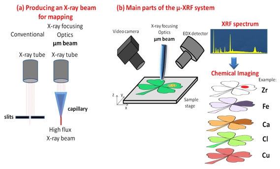
There are basically three ways of producing micrometric X-ray beams. They are: i) slits, ii) capillaries and iii) focusing mirrors. The first two concepts are presented below in (a). The slits lose most of the X-ray photons produced by the source, whereas the capillary optics collect the photons produced by the anode and concentrate them micrometric beam. The third possibility, although more sophisticated, presents higher costs and mostly available in synchrotron radiation facilities.
(a) Slits and capillary optical devices used to produced micrometric X-ray beams;
(b) Illustration of the main components of the µ-XRF system needed for our project highlighting how it will be employed for chemical imaging
The Figure above in (b) presents the main components of the EMU μ-XRF system. It shows the capillary X-ray optics, energy dispersive X-ray detector (EDX), video camera and automatic sample stage. This Figure also shows the concept of mapping usage in which the XRF spectrum is converted in chemical image uncovering the distribution and concentration of the elements along the sample. XRF images by absorption contrast are also feasible and might be explored during the non-destructive analysis of thick samples such as pods, seeds and fruits since it readily shows the presence of voids or differences of density inside of the sample.
X-ray fluorescence yield, and therefore limits of detection, depends, among other factors, on the number of photons reaching the sample. The micro beam configuration increases the X-ray flux up to 2-3 orders of magnitude compared to conventional XRF systems equipped with slits. It means that more diluted samples can be analyzed. Additionally, smaller amount of sample is required to perform the measurement since the beam contains a higher number of photons per unit of area.
It is possible to use the system to automate the qualitative and quantitative analysis of pellets or powders in Elisa plate. Compared to the most common analytical tools for quantification of metals such as atomic absorption (AAS) and inductively couple plasma optical emission (ICP-OES), our approach is cheaper and faster. This high throughput concept is illustrated below, which is a highly desirable analytical feature when a large number of samples has be analysed.
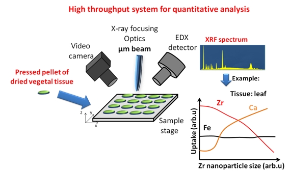
Illustration of the high throughput analysis method which may lead to the automation of the analysis of pellets, liquids or powders disposed in Elise plates.
µ-XRF vs competing techniques
There are other micro analytical methods which compete and complement the μ-XRF system. As almost everything in life they present advantages and disadvantages. The main alternatives to the EMU μ-XRF system are:
i) Scanning electron microscopy with X-ray energy disperse detector (SEM-EDX)
ii) Transmission electron microscopy with X-ray energy disperse detector (TEM-EDX)
iii) Particle induced X-ray emission (PIXE)
iv) Synchrotron based μ-XRF.
The EMU µ-XRF equipment presents some crucial advantages over SEM-EDX and TEM. We can highlight that µ-XRF does not suffer from charging effect, and therefore does not require metal deposition. Furthermore, the necessity of metallic coating would hinder the in vivo studies. µ-XRF is bulk sensitive, whereas SEM-EDX is limited to the first few micrometers below the surface, therefore the chemical information from µ-XRF is more comprehensive than that given by SEM-EDX. SEM-EDX and TEM operate under low and ultra-high vacuum, while µ-XRF maps can be done atmospheric pressure, which makes it possible to perform in vivo measurements.
SEM-EDX and TEM may cause sample damage due to the impact of electrons. Although SEM-EDX and TEM have higher lateral resolution (down to the nm range) than μ-XRF (μm), the detection limits for transition metals in capillary based µ-XRF can be 103 times better than those given by SEM-EDX. It happens due to the higher background resulted from the bremsstrahlung produced by electron excitation as shown below.
The analysis of biological tissues and cells by TEM require the use of contrasts, such as osmium tetroxide, uranyl acetate and lead citrate which may entail contamination of sample for XRF analysis. Moreover TEM spot size is too small (in nm range), whereas the EMU μ-XRF system presents beam size around 30-50 μm. It makes the μ-XRF perfectly suitable for scanning a vegetal cell which size is in the order of 10-100 μm, as well as specialized tissues such as veins in the range of mm.
SEM-EDX does not allow setting up the high throughput automatic quantitative analysis since it requires an operator to focalize the electron beam for each sample. This step is not necessary for the capillary µ-XRF system.
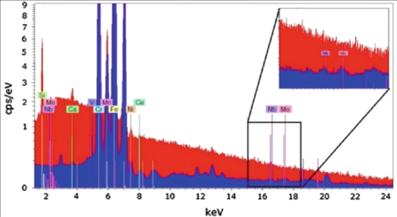
Comparison of two spectra of a stainless steel sample, one exited with electrons (red) and with another micrometric X-ray beam (blue). The excitation mode strongly influences de background and therefore the limit of detection. Figure 6.2 from M. Haschke, Laboratory Micro-X-Ray Fluorescence Spectroscopy, Springer 2014, p217.
PIXE and synchrotron based µ-XRF require large facilities rather than a compact laboratory and user friendly equipment like the here available EMU. These techniques are complementary, especially the synchrotron based µ-XRF which shares the same principles of requested equipment, however due to intrinsic properties of synchrotron light it has smaller beam size, lower detection limits and allows also performing speciation via X-ray absorption Spectroscopy. Nevertheless, beam time allocation in synchrotron facility is very competitive and only few samples can be measured.
Specifications and manual of the µ-XRF at LIN - CENA - USP
Comming soon.
Access to the EMU µ-XRF at LIN-CENA-USP
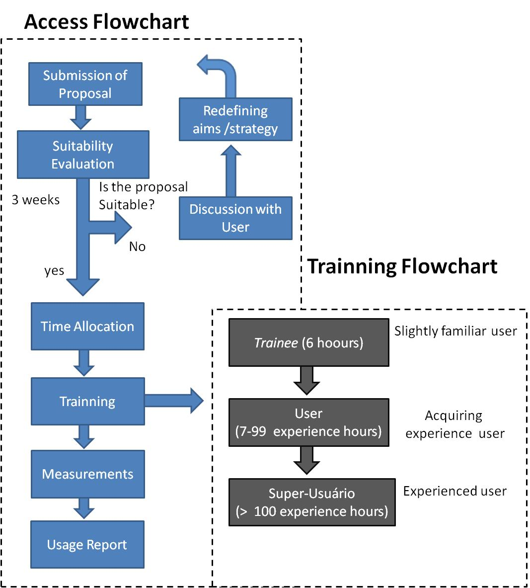
O The access process is described in the flow chart below.
Users are requested to fill the following application form click here to download . This procedure only intends to evaluate the suitability of the experiment; the process is coordinated by the EMU’s management board.
The filled form must be sent to microxrf@cena.usp.br. Nearly three weeks after submitting the form the user will receive a response and an attempt of allocation for the experiment. The EMU’s agenda is available at link to calendar.
The user is kindly requested to send a report click here to download no longer than two weeks after the measurement
Users will be ranked according to their experience since we have to project how much time will be dedicated to them during the measurements.
The users are also kindly requested to acknowledge the “Laboratory of Nuclear Instrumentation of CENA-USP for the use of the µ-XRF system granted by FAPESP process 2015/05942-0” in case of publications
Access to the EMU µ-XRF at LIN-CENA-USP
The raised funds will be used to purchase cuvettes, mylar and kapton films, sample holders, capillaries. It is also necessary to form a fund to keep the equipment running (maintenance or replacement of parts) after the end of the EMU project.
Type of user
| R$/machine hour
|
Researchers with proposals associated to a FAPESP grant
| 250,00
|
| Researchers at Universidade de São Paulo | 300,00 |
| Researchers at Public Research Institutions | 400,00 |
Other users
| 500,00
|
A payment slip and respective invoice/receipt will be provided by CENA-USP (you can use it in your financial reports for FAPESP or CNPq).
If you want just to run a test in one of your samples, please don’t hesitate in contacting us.
Management Board
The management board is in charge of:
I) Ensure the correct use of the equipment
II) Keep it running
III) Administrate the user´s access
1) Hudson Wallace Pereira de Carvalho
hudson@cena.usp.br
Centro de Energia Nuclear na Agricultura – CENA/USP
Principal Investigator
2) Marcelo Eduardo Alves
mealves@gmail.com
Escola Superior de Agricultura "Luiz de Queiroz" - ESALQ/USP
Associate Research
3) Eduardo de Almeida
edualm@cena.usp.br
Centro de Energia Nuclear na Agricultura – CENA/USP
Senior Technician
4) Susilaine Maira Savassa
susisavassa@gmail.com
Centro de Energia Nuclear na Agricultura – CENA/USP
Doctoral Student
User Comission
The user commission is intended to intermediate the contact between the user community and the management board. Its composition will be changed every two years, the process will be advertised in this web site and the new commission shall be approved by the Board of DVTEC-CENA.
1) Eduardo F. Molina
molina_ferreira@yahoo.com.br
Universidade de Franca
Professor
2) Helder Louvandini
louvandini@cena.usp.br
Centro de Energia Nuclear na Agricultura – CENA/USP
Professor
3) José Lavres Jr
jlavres@cena.usp.br
Centro de Energia Nuclear na Agricultura – CENA/USP
Professor
Associated Publications
Comming soon.